ESCI497Z:
UAS for Environmental Research and Monitoring
Post
Point Heron Colony Survey; Developing a Flight Plan with Mission Planner
Last
updated: 10/10/2022
Objective: Last
week, we looked at some imagery for the Post Point heron colony. The imagery
was obtained using a Solo flying at 120 m AGL. For this lab, I want you to
develop a flight plan to resurvey this site to obtain higher resolution imagery
by flying over the site at a lower altitude. You will be striving to fly
perhaps 10-40 m above the nests but developing a flight plan that stays well
clear of any obstructions (very tall trees). To do so, you will be using the
Mission Planner software. You will also need to review the FAA chart to
evaluate the airspace and any potential conflicts or regulatory issues. You
will be preparing a short (3-5 pages of text) write up describing your flight
plan.
PROCEDURES:
Step
1: Review the airspace. Go to J:/Saldata/ESCI-497/FAA_sectional_chart_Seattle.
Grab a copy of this file and place it in your workspace on C:/temp. Open this
file in ArcMap. For those of you who are not familiar with ArcMap, all you need
to do is open ArcMap, hit the add button ![]() and
select the Seattle84 North.tif file. After doing so,
this file will appear in the Table of
Contents section of your ArcMap window. You may need to click on the open
box next to the file name
and
select the Seattle84 North.tif file. After doing so,
this file will appear in the Table of
Contents section of your ArcMap window. You may need to click on the open
box next to the file name ![]() to
get the map to appear, like this
to
get the map to appear, like this

You will then need to zoom in to see the Bellingham area.
Determine the airspace class for the Post Point heron colony and for the
nearest controlled airspace. Your report should include a brief description of
the airspace and any potential conflicts or potential hazards from aircraft,
ground-based concerns. Be sure to include a clip from the FAA chart in your
report.
Keep
ArcMap open with the FAA chart. You will need it below.
Step
2: Mission Planner; Intro.
Mission Planner software is available on the computers
in SAL but it is also a free download available here: http://ardupilot.org/planner/docs/mission-planner-overview.html
This is the software that I use to program both our
3DR Solo and Aeromao Aeromapper for autonomous flight. There are lots of other
flight planning software packages out there but most are proprietary and rather
expensive. MP is quite good and an understanding of this software package would
help you use the others as well.
The link above takes you to the manual for MP.
I will skip over the steps for connecting MP to the
UAV but I’m happy to share this information with you if you are interested.
Step
3: Open Mission Planner
Open Mission Planner (MP). This brings up the Flight Data screen which provides a bunch
of telemetry and allows you to track the position of the UA during a flight.
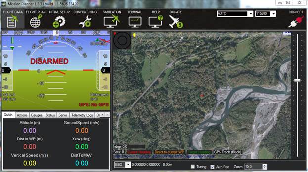
We want to focus on creating a Flight Plan, so click
on the ![]() button
to bring up this screen
button
to bring up this screen

You will see a different image on the screen (probably
a zoomed out image of the entire world). By using the Zoom slider and by
pushing and holding the left mouse to drag the image around, center the image
on the vicinity of the Post Point heron colony. Like this:

Prefetch:
If
you were working on a laptop that you planned to take out into the field for
this flight, you could right-click on the image (to bring up a list of
options), then go to Map tool-Prefetch.
This would enable you to download this image (at various zoom levels) to your
computer so you would have this orientation image available to you in the field.
YOU DO NOT NEED TO DO THIS NOW.
Step
4: Examine your imagery from last week in Arc
From Step 1 above, you should still have Arc open. Go
ahead and add your ortho and DEM that you created last week. Note from your
ortho that a sixth one of those big round things has been added to the sewage
treatment plant since the image above was acquired.
Based on the work you did last week, you know that the
heron nests are in the hardwood trees to the SW of the sewage treatment plant. Take a look at your DEM to figure out how tall the trees are
in the heron colony. Also note the height of the large conifers that are
located along the SW edge of the colony.
Your task is to design a new flight plan that will
provide higher resolution imagery than I obtained from my flight at 120m. I
would suggest shooting for a flight that is about 20-30 m above the nests. You
want a flight plan that provides full coverage of the area with the nests while
staying well clear of the tall conifer trees.
Step
5: Designing a Flight Plan in MP
Defining
a Polygon: Start by defining the boundary of your study area. In
the Flight Plan window, right-click
and select Draw Polygon-Add Polygon
Point. Then use left-clicks to add points that define your study area
boundary. Here is the polygon that defined the earlier flight at 120 m.

For your low-altitude flight, you will probably choose
to survey a smaller area. And you will note some scary-tall trees along the
southern margin of the polygon above.
Design
a Flight Plan: Right-click and go to Auto WP-Survey(grid). This brings up a
new window with a bunch of options

On the Simple
tab,
Camera:
We’ll
stick with the Canon S110-S120, even though we are using the S100.
Altitude:
select
your altitude in meters
Angle:
play
around with this, this sets the compass heading of the flight lines
Flying
speed: play around with this and note how the values in the Stats section on the bottom change. In
particular, note the “Photo every” value.
Note that we will use an intervalometer on our camera and that the
fastest that the camera can fire is once every 2 seconds. This means that you
can increase the flying speed until you get a “Photo every” value that is just
a bit above 2 seconds. However, you will need to come back to
this flying speed section after setting the photo overlap values (discussed
below).
Use
speed for this mission: make sure that this box is checked.
Add
takeoff and landing WPs: uncheck this box. We will be
manually doing the TO and landing with the Solo
Use
RTL: Check this box.
We want Solo to return to the launch site (but not auto land) after completing
the mission
Display:
Take
the defaults here. Note: be sure that the “Advanced Options” box in checked. If it isn’t,
you will not see the “Grid Options” or “Camera Config” tabs.

On the Grid
Options tab:
Distance between lines (m): This is the
distance between the flight lines. Note that this is greyed-out. This value
will automatically adjust when you set the Sidelap (below).
Overshoot (m): This is really only relevant for fixed-wing flights where you need
to give some additional space for the aircraft to make a turn and get lined up
for the next flight line. Leave this at zero for a quadcopter
Leadin(m): Same idea as overshoot. Just a
different way to achieve the same thing. You can play around with this to see
what it does (you can play with the Overshoot as well) but set it back to zero
for a quadcopter.
StartFrom: Toggle through these options. This
determines the location of your first waypoint.
Overlap and Sidelap:
Overlap is the overlap between successive photos on a single flight line. Sidelap is the overlap between adjacent images on adjacent
flight lines. These values are critical for creating a complete ortho image and
DEM in Agisoft. The rule of thumb from the Agisoft manual is at least a 70% sidelap and 80% overlap. But it is not that simple!
Geometry
matters: The figure below illustrates the field of view for a
camera either for successive photos on a single flight line or for images from
adjacent flight lines. Note that the footprint on the ground is such that the
images overlap by about 70%.

This is the overlap that the MP software is
calculating. It is done like this:


But what if
there is a forest canopy in your study area. Like this.

At the top of the canopy, the effective overlap is
reduced to about 30%!!!
If you do the calculations (which are a bit tedious)
for the example above (35 m spacing between flight lines, 120m altitude yields
an 80% sidelap) but you put in trees that are 30 m
tall, the effective overlap at the top of the canopy is reduced to about ~73%.
If you put in trees that are 60 m tall, the sidelap
is reduced to ~60%.
Calculating
Effective Sidelap at the top of the canopy:
So, how do you calculate the effective sidelap at the top of the canopy based on the sidelap on the ground? Figuring out how to do this is a bit
tedious.
ESL= effective sidelap (%);
we will solve for this
Hc=
flying height above canopy (m)
B=field
of view of camera across the flight
line (angle in radians) = 1.46 for this camera
W= camera footprint width across the flight line (m)
at top of canopy = Hc * B
S= distance between flight lines (m)
ESL= ((W-S)/W)*100

So, given the height of the trees in the colony, you can
calculate the effective sidelap at the top of the
canopy for a ground sidelap of 80%. Then reduce the
ground based sidelap and recalculate the effective sidelap at the top of the canopy. Keep fiddling around
until you get an effective sidelap at the top of the
canopy of about 80%. As you will see, as you adjust the % sidelap
the software will change the distance between the flight lines.
Or,
rearrange and solve for S given a desired ESL to get
S = W – (W*ESL)/100
Calculating
Effective Overlap (Frontlap) at the top of the
canopy:
Adjusting the Overlap (Frontlap)
involves changing the distance between photos along an individual flightline.
This is done by either changing the flight speed or by adjusting the time
between photos. For this camera, the best that we can do is to take a photo
every two seconds. So this means that our only option
is to alter the flight speed. But
first, we need to calculate the distance
between photos. If our photos were square, we could just look at the distance
between flight lines that we came up with above. But our images are not square;
they are rectangles and wider than they are tall (“landscape” rather than
“portrait” mode). So, here is the calculation:
DI = distance between images along the flight line
(m); we will solve for this
H = flying height above the canopy (m)
B=field
of view of camera along the flight
line (angle in radians) = 1.09 for this camera
L= camera footprint length along the flight line (m) =
H * B
EFL = effective frontlap (%,
not as a proportion)
DI = L – (EFL*L)/100
After calculating DI, (which is in meters) simply
divide by 2 seconds (the max trigger interval for the camera) to get the flight
speed (in m/sec) that is required to obtain the desired % overlap along the
flight line.
Effective Image
Resolution:
The report that is generated by Agisoft provides the
image resolution (pixel size) on the ground. For the imagery that you worked
with last week (flight at 120 m) the resolution was 3.36 cm. Ground resolution
is related to the flying height and the instantaneous field of view of the
sensor and this formula:

Note that the Instantaneous field of view
is NOT the same as the total field of view for the camera that you used above.
The total field of view for the camera includes all of
the individual pixels that make up an image either across track (image width)
or along track (image height). The Instantaneous field or view (IFOV) is the width
and height of a single pixel in the image. So, based on the flying height
of 120 m and the reported pixel size of 3.36 cm (or 0.0336 m) we can calculate
the Instantaneous Field of View (IFOV) of our camera.
B
= D/H
B
= 0.0336
m/120 m
B
= 0.00028
The resolution reported by Agisoft only holds for
areas where the camera is at the target flying height. For portions of the
scene that include a tall tree canopy, the effective resolution will actually
be much better (smaller pixel size). So, for this 120 m flight, and the areas
where the tree canopy is about 30 m tall, the effective pixel size is:
D
= H * B
D
= 90 m * 0.00028
D
= 0.0252 m = 2.52 cm
So, for your flight plan, calculate the pixel size on
the ground and the effective pixel size at the top of the tree canopy, where
the nests are.
Image
“Smear:”
Yet another thing to consider is Image “Smear.” This
is related to how far the quadcopter moves while the camera shutter is open.
For example, if you are flying at 10 m/second, this translates to 1000
cm/second. If your camera is using a shutter speed of 1/1000th
second, this means that the quadcopter will travel 1 cm while the shutter is
open. On the other hand, if you use a shutter speed of 1/250th
second, your quadcopter will travel 4 cm while the shutter is open. If you have
a pixel size of 2 cm, this would result in a fair amount of image
smear/blurring. I’ve not been able to find much guidance on rules of thumb for
this one but I’m inclined to think that it would be
good to keep your image smear to less than the size of your pixels. How much
less? I’m not sure.
Screenshots:
You should take screenshots (using the snipping tool)
of your flight plan before moving on. You will need these screenshots for your
report. After you hit the Accept
button on the Simple tab, you cannot
come back to make changes. So, I would suggest that you take screenshots that
include the details from both the “Simple” and “Grid Options” tabs as well as
the “Stats” and a view of your flight plan. For example, here are the details
from my flight at 120 m. Note that, when I developed this flight plan, I had no
information about the tree canopy height so I just used a default setting of
80% overlap and sidelap and I just made an arbitrary
decision about the flying speed. You will be able to make a more informed
decision about each of these parameters.


When you have a flight plan that you are happy with,
hit the Accept button on the Simple tab. This takes you back to you Flight Plan screen where you can
inspect the details of your waypoints and save
your WP File. In class, I’ll show you a few other things on this page.
What
to turn in: I want you to prepare a report documenting
your flight plan for obtaining imagery of the portion of the study area that
contains the heron nests. An adequate description of your flight plan should
include 3- 5 pages of text plus numerous figures. Your report is due at the
beginning of class next week. I do not want a hard copy of your report. Simply
send it to me via email as an MS Word file.
Report
Outline/issues to discuss:
-airspace issue
- obstructions in the study area (tall trees to avoid;
where and how high; your polygon that avoids these obstructions but covers the
area containing nests
- discussion of calculations needed to obtain desired
image overlap at the top of the tree canopy
-brief discussion of stats for your flight plan
(flight duration, distance, etc. can you complete the flight with a single
battery?)
- effective image resolution at the top of the canopy
for your flight plan